
Computer vision is a rapidly advancing field that has the potential to revolutionize how we interact with the world around us.
Thanks to recent breakthroughs in artificial intelligence and machine learning, with Generative AI computers can now interpret and comprehend images and videos with remarkable accuracy. Facial recognition systems are just one of the many practical applications enabled by computer vision technology and AI morphing.
This article overviews two state-of-the-art AI-based face morphing techniques and their advantages and limitations. It was written by Oleksandr Mamchich, the Head of the Mobile Development at Syndicode, also an Artificial Intelligence enthusiast.
Virtual makeup
Face morphing is a process of editing face features yet keeping them realistic even with animation. Users often call it “virtual makeup” or “AI-powered makeup.”
There are various approaches to implementing virtual makeup in a mobile application, and our blog will cover the two most popular ones. One is based on planar transformations (Face Morphing 2D or FM2D), and the other involves volumetric transformations (Face Morphing 3D or FM3D). Then we will compare them to highlight the advantages and disadvantages of each approach.
Both approaches have something in common—they both are implemented with a graphics API Metal and use CoreImage face detection.
Face Morphing 2D (FM2D)
FM2D is built on top of a plain grid-warping approach. Our example application is developed for iOS and requires both graphics rendering and custom GPU code, so utilizing Metal is the most viable option. It is a powerful tool capable of handling transformations and texture mappings.
Metal’s primary purpose is rendering textured polygons. Each polygon has vertices with a set of parameters to represent its position in space and define its texture.
You can look at a polygon as a textured quad, a plastic sheet that may be infinitely stretched but will always preserve the texture ‘drawn’ on its surface. This is called warping.
Let’s break this abstract art image into several separate quads. Now, we can move the vertices of each quad independently to achieve more complex warping.
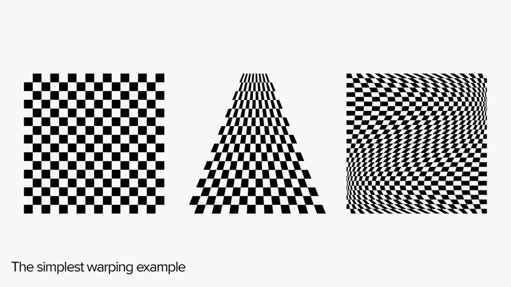
The higher the grid resolution, the smoother the warping, creating a sense of continuous, seamless texture in an image of any size.
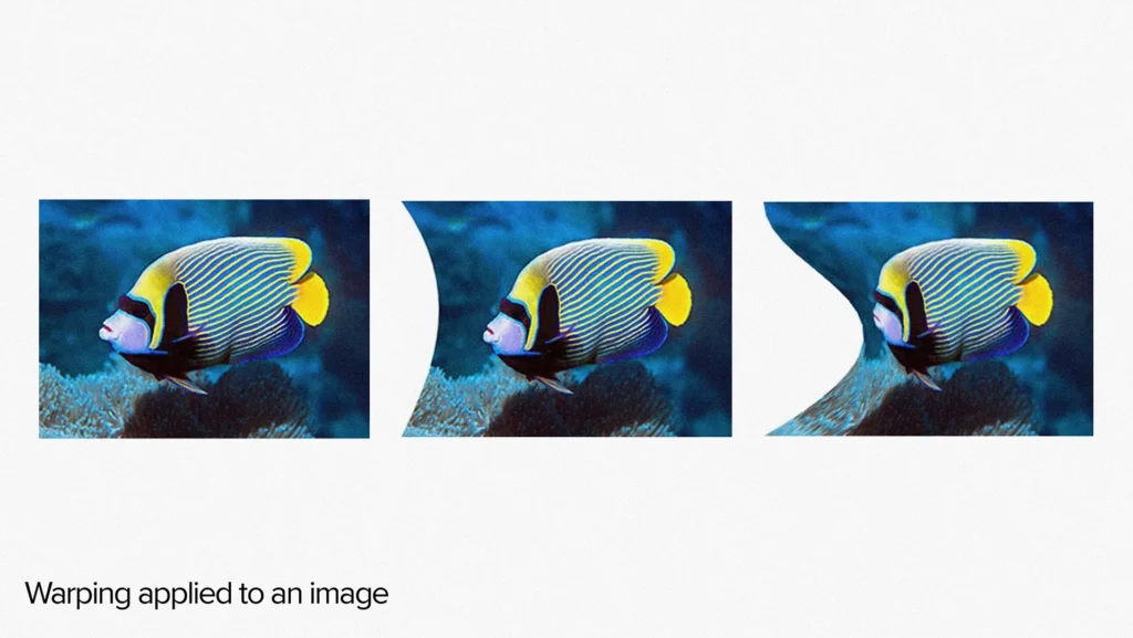
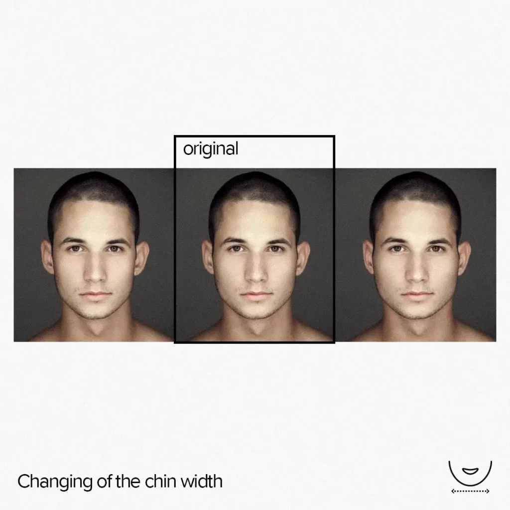
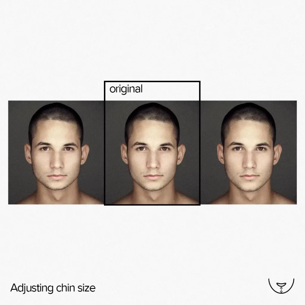
Let’s warp an image of a human face. We can apply effects like scaling, bulging, twisting, smudging, etc., by adjusting the positions of particular vertices of the warp grid. However, before applying an effect, we must first identify the location of the face within the image.
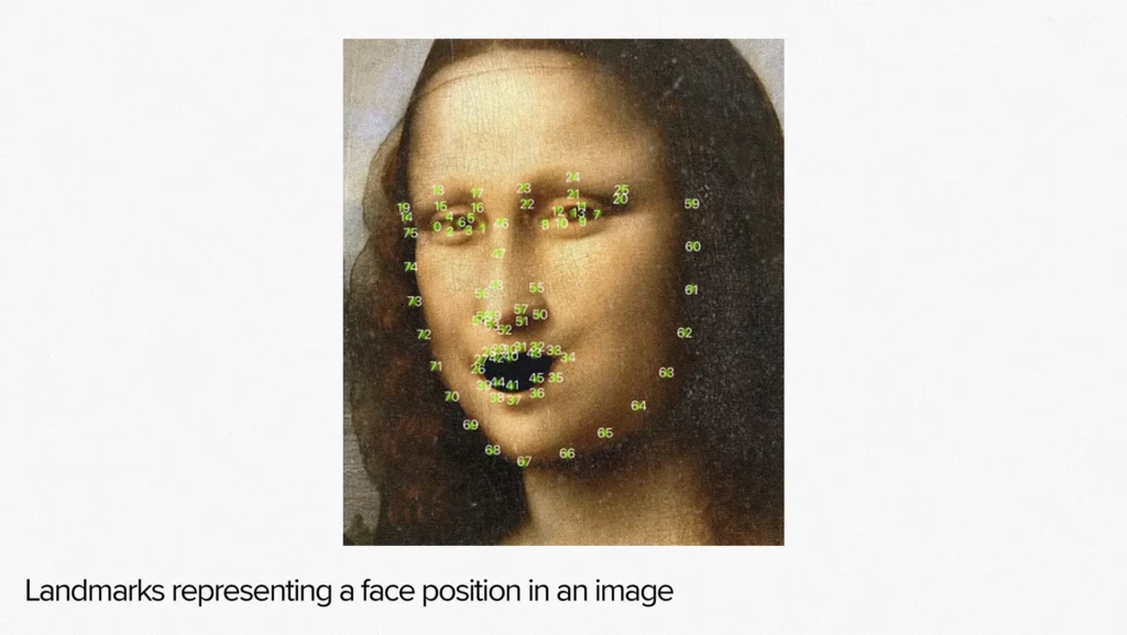
This is where the Core Image technology comes in. It detects the presence of a face in an image and provides an array of points in the image’s coordinate space. These points mark particular face areas and are referred to as landmarks. These landmarks are used to determine where to apply a particular effect.
In our project, we had 20 face feature effects to apply, and each effect was built as a separate formula with the following structure.
typedef struct
{
    float features[FeaturesCount];
    vector_uint2 resolution;
    Vector_float2 size;
    float2 landmarks[LandmarksCount];
} Face2dUniforms;

float2 compute_feature_0(float2 ip, float2 cp, const Face2dUniforms& uniforms);
The struct `Face2dUniforms` located before the `features` field in the code snippet above contains values from -1 to 1. These values represent the strength of the effect application, where -1 stands for the maximum negative application, 0 means no effect, and 1 is the maximum positive application.
The ‘resolution’ field specifies the grid resolution, the `size` field represents the physical size of the face in the virtual world coordinates, and the `landmarks` field contains Core Image landmarks. A user can morph the face on an image by applying effects one by one.
typedef struct
{
    vector_float3 pos;
    vector_float2 tex;
} MetalVertex;

void compute_makeup2d(MetalVertex* vertices,
                const Face2dUniforms& uniforms,
                int index)
{
    MetalVertex dv = create_vertex(index, uniforms);
    float2 pos = dv.pos.xy;

    dv.pos.xy += compute_feature_0(pos, dv.pos.xy, uniforms);
    dv.pos.xy += compute_feature_1(pos, dv.pos.xy, uniforms);
    …

    vertices[index] = dv;
}
Attentive readers may have noticed that we use three coordinates to specify positions of planar objects instead of two, set texture coordinates but never use them, and create vertex by just index.
The reason for doing so is simple: we are using a Renderbuffer to store data for rendering in this example. The specified functions provide the pseudocode for Metal Compute Shaders, allowing us to manipulate and transform the data in the Renderbuffer.
To build the grid, we use the `resolution` and `size` uniforms to generate vertices and assign each vertex an index. Then, we apply various effects and transformations to each vertex, resulting in a set of morphed points. These points are then stored in the Renderbuffer.
Finally, we use other Metal shaders, such as the Metal Vertex Shader and Metal Fragment Shader, to render the image using the data stored in the Renderbuffer.
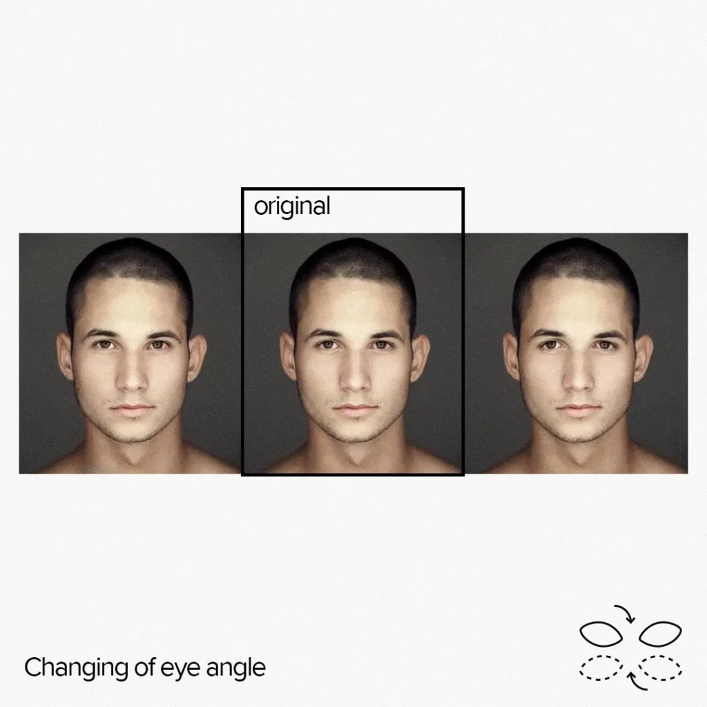
The result of 2D morphing


Why did we choose to use a GPU-only implementation instead of a CPU-based one?
The reason is that in order to achieve seamless effects, the grid resolution needs to be at least 512 vertices along the longer side, with an optimal number of 1024 vertices. Additionally, the logic that needs to be applied to each vertex is quite complex: the code for a vertex (if it’s affected by all effects) may be more than 1000 lines long.
However, it is worth noting that the majority of vertices do not fall within the effects area.
The main advantage of using a GPU-based approach is its high performance and relative simplicity. With this implementation, we achieved 20 FPS for camera input on an iPhone SE and a stable 30 FPS for processing a 4K static image on the same device.
On iPhone X and later models, it was always above 30 FPS for processing camera input and high-resolution static images. Quite impressive, isn’t it?
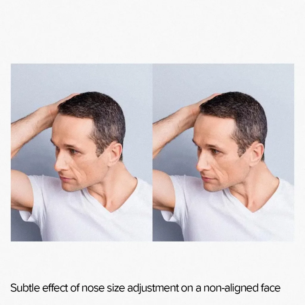
One downside of this approach is that it can lead to subpar results for unaligned faces. If the face is not directed straight into the camera, the effect may either be subtle or create artifacts.
It happens because we have to work with a 3D object as if it were a 2D object. Yet, the representation of the far side of a face in a three-quarter view differs significantly from that of the near side.
Additionally, effects applied to a 2D image have a spread along the grid, whereas, for a 3D face, the distribution will follow the 3D surface. As a result, 2D transformations applied to eyes, for example, tend to affect surrounding pixels more than the corresponding 3D transformation.
Face Morphing 3D (FM3D)
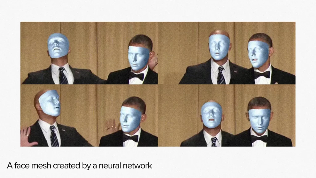
Face Morphing 3D implies working with a 3D model of a face. However, Core Image or Vision is unsuitable for this task. Instead, a third-party neural network must be used.
The neural network takes a single face area on the image as input and produces a face mesh as output. A mesh is a set of triangles that make up a single object. Here’s an example to help illustrate the output.
In this case, the process of face morphing is much more complicated compared to the 2D case. The first step is to determine the position of every face on an image. For our project, we used Visio as it has an option for fast face area detection.
VNImageRequestHandler* handler = nil;
handler = [[VNImageRequestHandler alloc] initWithCGImage:image.CGImage
                                             orientation:orient
                                                 options:@{}];

VNImageBasedRequest* faceRequest = nil;
faceRequest = [[VNDetectFaceRectanglesRequest alloc] init];
faceRequest.revision = 2;

NSError* error = nil;
[handler performRequests:@[faceRequest] error:&error];
To define the position and size of a face on an image, we are using the `VNFaceObservation.boundingBox` property.
However, through a series of tests, we’ve discovered that aligned faces result in much higher accuracy when generating the mesh from our neural network model. To achieve this alignment, we introduce a new value called `VNFaceObservation.roll`, which allows us to cut out the face area from the image and rotate it using the `-roll` angle.
Further, we add the ‘TFLite’ framework to the project either through a pod or manually and ensure the model is fully loaded with properly allocated tensors. If everything is set up correctly, we can convert the uint8 4-channel image into a float32 3-channel image and input the face area sub-image into the tensor. Finally, we run the model’s inference to generate the mesh.
The model has multiple outputs, but we need only two of them:
- The mesh is represented by a vertices array containing the location of vertices in the face area coordinate system;
- The face pose is set by a matrix.
The face mesh is in the face area coordinate system, which means it is translated and rotated. To adjust for this, we multiply every vertex of the mesh by a reverse matrix of translation based on the `boundingBox`’s location and rotation by the `-roll` angle.
Matrices
At this point, we may have to dive into matrix math since we will have a lot of it later.
Every mesh is made up of vertices, with every vertex having a coordinate in some coordinate system. Typically, this coordinate system is referred to as ‘object coordinates’. When rendering a mesh, it is usually placed in a world.
In our case, the world coordinate system is based on an image coordinate system. The point O (0; 0) corresponds to the image’s zero pixel, and the scene is restricted by the (width; height) point, where width and height values equal the dimensions of the image.
To switch from an object coordinate system to the world one, we can use a single matrix product, regardless of how different those coordinate systems are. If the world coordinate system was obtained through a series of simple steps such as translation, rotation, and scaling, the matrix can be evaluated by multiplying the translation matrix by the rotation matrix and then by the scale matrix.
In other words, we can merge several matrices into one by multiplying them. The resulting matrix will perform the same transformations as if we have applied all initial matrices one after the other.
In our case, we’re moving from the coordinate system of the face bounding box to the image coordinate system. To achieve this, we translate the point O to the bounding box location, followed by a rotation of the axes by the `-roll` angle.
Thus, the image-to-face translation matrix can be evaluated as MItoF=MT*MR. The face-to-image translation matrix can be obtained by taking the inverse of MItoF, which can be represented as MFtoI=(MItoF)-1. By multiplying each vertex of the mesh by MFtoI, we can translate the mesh to the image coordinate system.
Currently, we have a mesh for each face in the coordinate system of the image. However, these meshes have varying sizes and orientations, so we need to make corresponding adjustments to work with them effectively.
To simplify the process, we will put them back into their object coordinate space but under different conditions. To build this coordinate system, we need to create three matrices and multiply them together:
- Find the geometrical center of a mesh and translate it to the (0;0) point;
- Determine the roll angle of a mesh using the face pose matrix and rotate it by `-roll`;
- Calculate the bounding box of face mesh and scale to fit within the (-1;1) range along the X-axis while preserving the aspect ratio along the Y-axis.
The resulting product of these matrices will transform the face mesh into a coordinate system with the following conditions:
- The face mesh will be oriented upwards, which simplifies evaluations. The up vector will always be (0; 1), the left will always be (-1; 0), and so on;
- All faces can be considered to be of the same size, with only the height differing (the Z-axis is irrelevant);
- All faces will be centered at the (0; 0) point, which can significantly simplify later evaluations.
For each frame, we need to render a face mesh onto the image coordinate system. To accomplish this, we will multiply the meshes by the inverse matrix of the one described above. Since GPU will do the calculation, it can be considered to have a near-zero evaluation cost.
Back to face morphing
To apply face morphing, we need to adjust specific vertices of the face mesh. It is done similarly to adjusting the warp grid but is a bit more complex.
When performing 2D morphing, we can evaluate the effect propagation gradient along the warp grid plane as a function of Euclid distance. However, for 3D morphing, the effect must be propagated along a 3D surface, which cannot be done with a simple formula.
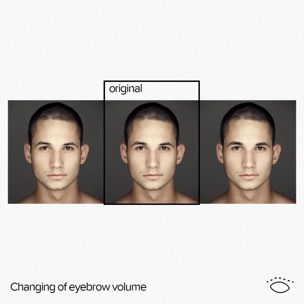
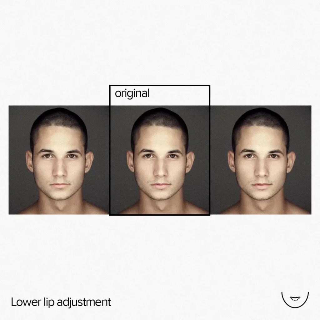
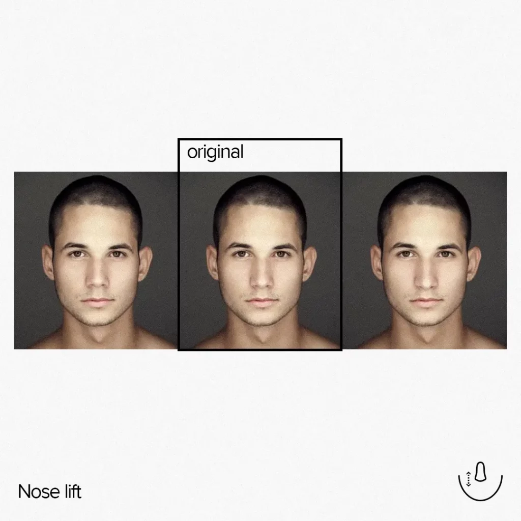
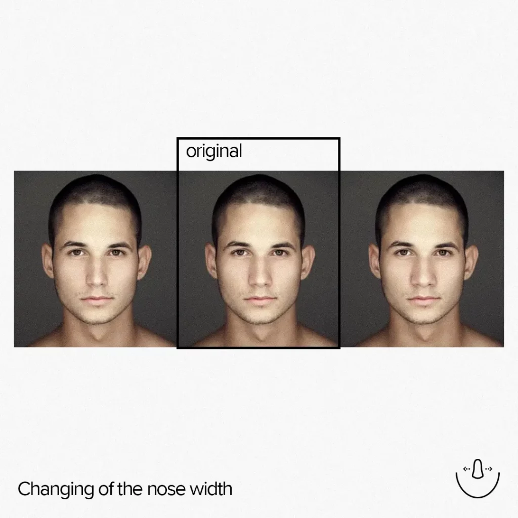
Therefore, we use special markup files to bake the propagation gradients offline. The morphing of the 3D mesh is implemented with six separate calls, one for each facial feature: eyes, mouth, eyebrows, nose, nose length, and chin, each of which has different markups.
struct MakeupFaceInfo
{
};

float3 compute_feature_0(float3 pos, float3 nor, float hardness,
                         float value, const MakeupFaceInfo& face)
{
    …
}

float3 compute_feature_1(float3 pos, float3 nor, float hardness,
                         float value, const MakeupFaceInfo& face)
{
    …
}

…

void compute_feature(MetalVertex* input,
                     FaceMarkupInfo* markup,
                     MetalVertex* output,
                     const ComputeMakeupUniforms& uniforms,
                     const MakeupFaceInfo& faceInfo,
                     int index)
{
    FaceMarkupInfo mi = markup[index];
    uint vi = mi.index;


    MetalVertex vSrc = input[vi];
    MetalVertex vDst = output[vi];

    vDst.pos += compute_feature_0(vSrc.pos, vSrc.nor, mi.hardness,
                                  uniforms.features[Id_Nose0], faceInfo);
    vDst.pos += compute_feature_1(vSrc.pos, vSrc.nor, mi.hardness,
                                  uniforms.features[Id_Nose0], faceInfo);
    …

    output[vi] = vDst;
}
The `compute_feature_X` functions take the following inputs:
- `pos` – the position of a vertex in 3D space;
- `nor` – a surface normal vector;
- `hardness` – a value that comes from the `markup` array;
- `value` – a parameter representing the effect magnitude of the makeup feature, ranging from -1 to 1;
- `face` – a parameter that contains information about the coordinate system, including landmarks and precalculated data necessary for the application of an effect.
The `compute_feature` function uses
- `input` – the input vertex buffer;
- `markup` – the array of the effect propagation gradient;
- `output` – the output vertex buffer;
- `uniforms` – a parameter that contains information about the current effects’ intensities;
- `faceInfo` – a parameter that contains information about the coordinate system, including landmarks and some precalculated data necessary for the application of an effect;
- `index` – the index of the current vertex in a mesh.
The above code fragment is a simplified pseudocode to help explain the logic of Metal computing shaders that are used to apply mesh morphing.
The result of 3D morphing
In this project, we couldn’t afford in-place morphing. Instead, we had to separate the input and output buffers in order to apply a sequence of morphing computing shaders. Yet, this extra step didn’t negatively impact the performance because we only had to process the affected vertices stored in markup rather than iterating through all vertices as in the 2D example.
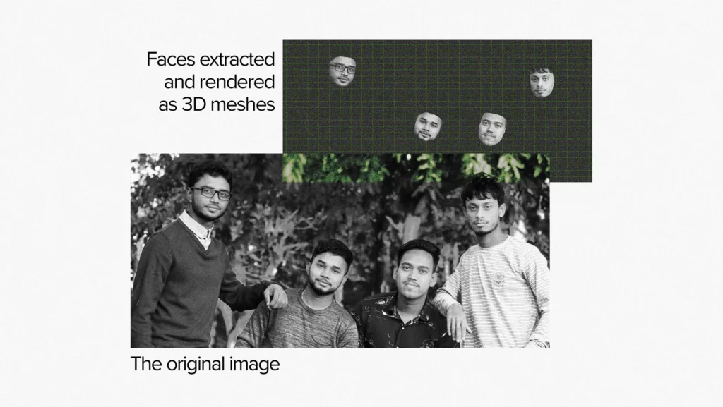
Once each face has been morphed, we can render them by passing multiple face meshes, along with their object-to-world matrices, to a vertex shader. If we render meshes without morphing, they will appear as shown in the following image.
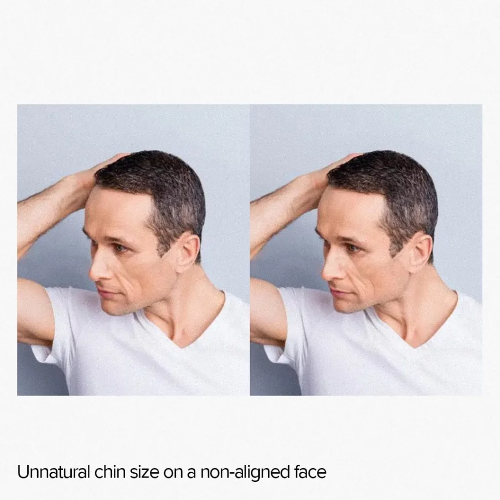
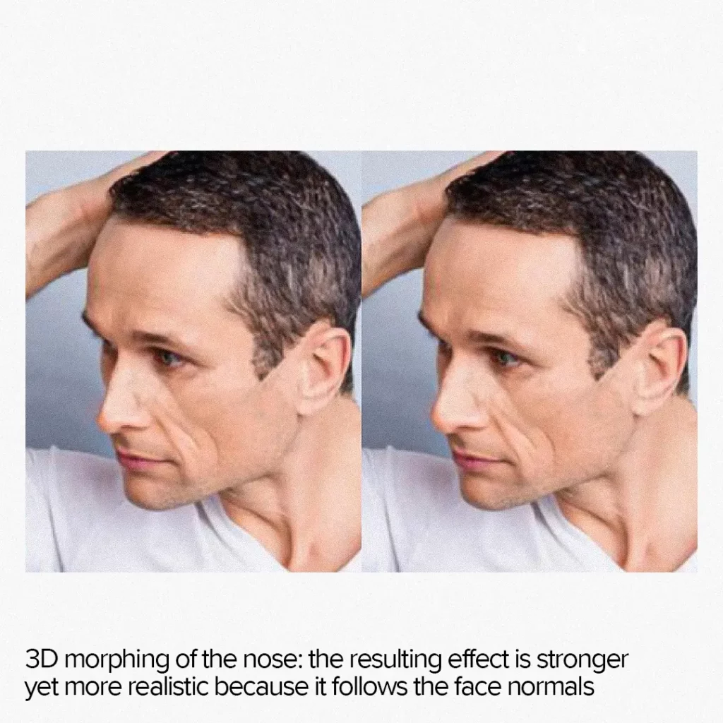
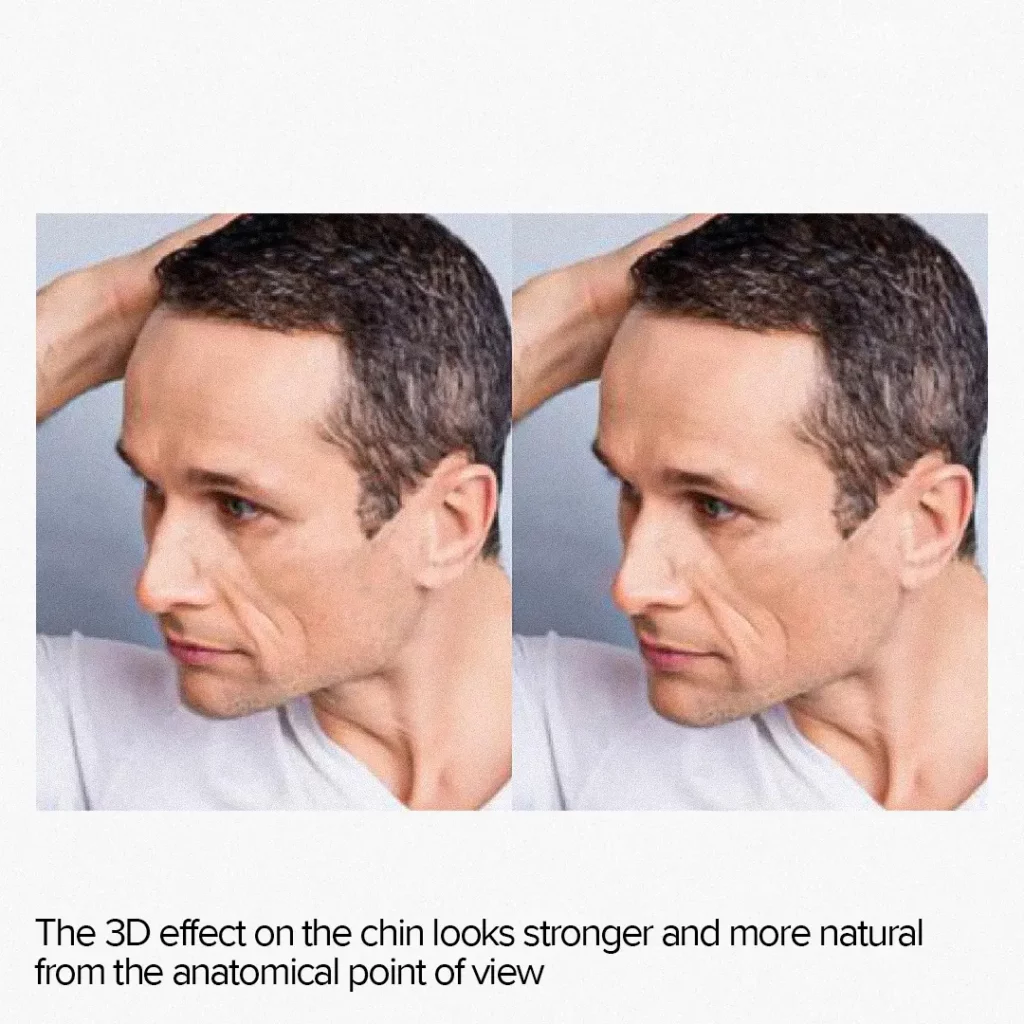
3D face morphing allows for stronger and more natural effects on unaligned faces. For example, feature growth effects appear more realistic as they follow the normals of the face, producing a true dilation effect instead of simple scaling relative to a central point.
Additionally, when AI morphing overlays the background image, the 3D technique produces a more natural and sharper output. While 2D morphing simply distorts the planar image, 3D morphing moves the entire 3D model to a new location keeping the background intact.

Disadvantages of 3D morphing
There are two main disadvantages to 3D morphing:
- Performance is highly affected despite most of the processing being done on the GPU. Each face requires a series of steps to apply an effect, including a Vision call to detect the face, a neural network call to analyze the facial features, a computing sequence to apply the effect, and a rendering call to display the modified face. In addition, some CPU work is required to prepare the rendering process.
- High memory usage due to multiple temporary buffers and a pretty big neural network growing the size of both RAM and the bundle. This is especially noticeable when supporting a wide color gamut for photos.
Only the latest devices, such as iPhone 12 and later, can maintain real-time multiple-face camera capture processing. Nevertheless, the speed is adequate for static image processing, even for older devices, such as iPhone 8 and earlier.
So, for the actual project, it was decided to use 2D morph for real-time camera capture and 3D for static images.
Summing up
AI face morphing has become increasingly popular across different industries and applications. One of the most widespread uses of ai morph is face authentication, which is commonly associated with unlocking mobile devices but is also used in crowd surveillance and law enforcement.
Social media platforms have also adopted face morphing techniques to improve photos or create fun filters that allow users to transform their faces. Additionally, the healthcare industry benefits from face recognition technology to diagnose diseases that cause detectable changes in physical appearance.
Syndicode is a software development company that covers these areas and more, offering custom solutions for face recognition and morphing technology across various industries.